| Title and Reference |
Abstract |
HAL/S Documentation-
HAL/S Compiler System Specification
-
HAL/S Language Specification
-
HAL/S Programmer's Guide
-
HAL/S-FC User's Manual
-
Programming in HAL/S
|
|
|
Shuttle ALT Free Flight 1: GPC 2 Failure
|
Introduction
The separation event was marked by a sharp, but not loud,
explosive sound and a brief, sharp, upward lurch. Neither the noise nor
the jolt were particularly distracting and did not affect the
accomplishment of the planned procedures. Immediately after the
separation event, a master alarm occurred and a computer caution and
warning light, a computer annunciation matrix column on general purpose
computer 2, and a big "X" on cathode ray tube 2 were noticed . |
|
Shuttle ALT Flight 1A: GPC 3 Failure
|
Summary
General purpose computer 3 failed during preflight checks for captive-active
flight 1A on June 17, 1977, at 14:33:04. The central processing unit and
input-output processor both stopped executing. No built-in test equipment
error indications were generated. Troubleshooting, including
thermal cycling, has not caused the problem to recur. The problem cannot be
further isolated by analysis, so the actual cause cannot be determined.
|
|
Space Shuttle Technical Conference
Lyndon B. Johnson Space Center
June 28-30, 1983
NASA Conference Publication 2342
General Chairman: Aaron Cohen |
Abstract
This publication is a compilation of the papers prepared for the Space
Shuttle Technical Conference held at the NASA Lyndon B. Johnson Space
Center, Houston, Texas, June 28-30, 1983. The purpose of this conference was
to provide an archival publication for the retrospective presentation and
documentation of the key scientific and engineering achievements of the
Space Shuttle Program following the attainment of full operational status by
the National Space Transportation System.
To provide technical disciplinary focus, the conference was organized
around 10 technical topic areas: (i) Integrated Avionics, (2) Guidance,
Navigation, and Control, (3) Aerodynamics, (4) Structures, (5) Life Support,
Environmental Control, and Crew Station, (6) Ground Operations, (7)
Propulsion and Power, (8) Communications and Tracking, (9) Mechanisms and
Mechanical Systems, and (10) Thermal and Contamination Environments and
Protection Systems.
The papers in each technical topic which were presented over the 3-day
conference period provide a historical overview of the key technical
problems and challenges which were met and overcome during the development
phase of the Space Shuttle Program. Taken as a whole, these papers provide a
valuable archival reference to the magnitude and scope of this major
national achievement.
|
|
Inadvertent Firing of L1L, L1U, R4U, F3L, and F3U (ORB)
|
Power-on Reset Problem
Primary reaction control system (RCS) thrusters L1L, L1U, R4U, F3L, and F3U
inadvertently fired simultaneous 80-msec pulses at 035:11:41:06 G.m.t.
(001:06:19:02 MET) when aft flight controller power was switched on. The
firing was consistent with a +Y/+Z translation command response. The crew
reported that the aft station translational hand controller (THC) had not
been deflected. |
|
Single Event Upsets for Space Shuttle Flights of New General Purpose
Computer Memory Devices
P.M. O'Neill and G.D.Badhwar
NASA
IEEE Trans. on Nuclear Science, Vol. 41., No. 5
October 1994
pp. 1755 - 1764
|
Abstract
The replacement of magnetic core with a well characterized
semiconductor memory in the Space Shuttle orbiter general purpose computers
(GPC's) has provided a wealth of on-orbit radiation effects data since 1991.
The fault tolerant GPC's detect, correct, and downlink memory upset status
and orbiter position information every few seconds, giving us the ability to
correlate 1400 upsets to date with altitude, geomagnetic latitude, and solar
conditions. The predicted upset rate was computed by a modified path-length
distribution method. The modification accounts for the Weibull distribution
cross-section (rather than a single upset threshold) and the device
sensitive volume thickness. Device thickness was estimated by the method
normally used to account for edge effects at the upset cross-section
discontinuity that occurs at ion changes. A galactic cosmic ray environment
model accurately models the average particle flux for each mission. The
predicted and observed upset rates were found to be in good agreement for
sensitive volume thicknesses consistent with the device's fabrication
technology. |
|
The "Bug" Heard 'Round the World
Jack Garman
NASA, Johnson Space Center
ACM Software Engineering Notes
October, 1981, pp. 3-10. |
Introduction (excerpts)
Discussion of the software problem which delayed the first Shuttle
orbital flight.On April 10, 1981, about 20 minutes prior to the scheduled
launching of the first flight of America's Space Transportation System,
astronauts and technicians attempted to initialize the software system which
"backs-up" the quad-redundant primary software system ......and could not.
In fact, there was no possible way, it turns out, that the BFS (Backup
Flight Control System) in the fifth onboard computer could have been
initialized properly with the PASS (Primary Avionics Software System)
already executing in the other four computers. |
|
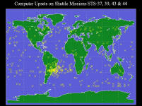
Computer Upsets on Shuttle Missions STS-37, 39, 43, and 44
From
http://www.ngdc.noaa.gov/stp/GOES/sts.pdf |
 |
|
Distributed Processing on the Space Shuttle:
A Case Study
P. 5. Schoonmaker
McDonnell Douglas Technical Services Co., Inc.
Houston, Texas
AIAA Paper 81-2140 |
Abstract
This paper describes a study of centralized vs. distributed
processing approaches to the design and integration of a new Space Shuttle
Orbiter subsystem -- the Power Extension Package (PEP), a 25-kw solar array.
The objective of this study was to determine the "best" a l location of PEP
monitoring and control functions between the existing Orbiter Systems
Management (SM) computer and an autonomous PEP processor. Four candidate
functional configurations were defined, and a subjective, life-cycle
assessment of the re1ative merits o f these candidates was performed by the
study team. We concluded that the optimum configuration will (a) include
substantial processing "intelligence" in the PEP processor, and (b) make use
of SM computer "standard services". |
|
A GPS Receiver Upgrade For The Space
Shuttle – Rationale And Considerations
John L. Goodman
United Space Alliance LLC
40th AIAA/ASME/SAE/ASEE Joint Propulsion Conference and Exhibit, Fort
Lauderdale, FL, July 11-14, 2004.
AIAA-2004-3911 |
Abstract
In the mid 1990s, a 5 channel Global Positioning System (GPS) receiver was
integrated into the Space Shuttle avionics system due to the anticipated
start of Tactical Air Control and Navigation (TACAN) phase-out in the year
2000. While the early 1990s technology level receiver adds redundancy and
flexibility to the navigation process, and improves safety at emergency
landing sites, new capabilities in modern GPS receivers would further
enhance Shuttle navigation. All-in-view satellite tracking, new GPS signals
and ground and space based augmentation systems would provide a more robust
GPS navigation solution for the orbiters, particularly if future missions
call for automated landings, or on-board precision orbit determination. |
Lessons Learned From Flights of “Off the Shelf” Aviation Navigation Units on
the Space Shuttle
John L. Goodman
NASA Johnson Space Center, United Space Alliance, LLC
shuttle_gps_lessons_learned_may_02.pdf |
Abstract
The Space Shuttle program began flying atmospheric flight navigation units in
1993, in support of Shuttle avionics upgrades. In the early 1990s, it was anticipated that
proven in-production navigation units would greatly reduce integration, certification and
maintenance costs. However, technical issues arising from ground and flight tests
resulted in a slip in the Shuttle GPS certification date. A number of lessons were
learned concerning the adaptation of atmospheric flight navigation units for use in
low-Earth orbit. They are applicable to any use of a navigation unit in an application
significantly different from the one for which it was originally designed. Flight
experience has shown that atmospheric flight navigation units are not adequate to support
anticipated space applications of GPS, such as autonomous operation, rendezvous, formation
flying and replacement of ground tracking systems. |
The Space Shuttle and GPS – A Safety-Critical Navigation Upgrade
John L. Goodman
NASA Johnson Space Center, United Space Alliance, LLC
shuttle_gps_n_cots.pdf |
Abstract
In 1993, the Space Shuttle Program selected an off-the-shelf Global Positioning
System (GPS) receiver to eventually replace the three Tactical Air Navigation units on
each space shuttle orbiter. A proven, large production base GPS receiver was believed to
be the key to reducing integration, certification, and maintenance costs. More GPS
software changes, shuttle flight software changes, and flight and ground testing were
required than anticipated. This resulted in a 3-year slip in the shuttle GPS certification
date. A close relationship with the GPS vendor, open communication among team members,
Independent Verification and Validation of source code, and GPS receiver design insight
were keys to successful certification of GPS for operational use by the space shuttle. |
A Software Perspective on GNSS Receiver Integration and Operation
John L. Goodman
NASA Johnson Space Center, United Space Alliance, LLC
sw_perspective_on_gnss_rcvr_int_op.pdf |
Abstract
The GNSS industry is focusing on potential threats to satellite navigation
integrity, such as intentional and unintentional interference, signal-in-space (satellite)
and ground support infrastructure anomalies, shared spectrum issues, and multipath. The
experience of the International Space Station (ISS) program, the Space Shuttle program,
the Crew Return Vehicle (CRV) program and other users of GNSS indicate that navigation
outages due to receiver software issues may pose as great a risk, if not more, to the user
than threats currently under study. The improvement in GNSS receiver tracking
capability and navigation accuracy has been accompanied by an increase in software
quantity and complexity. Current and future GNSS receivers will interface with multiple
systems that will further increase software complexity. Rather than viewing GNSS receivers
as “plug and play” devices, they should be regarded as complex computers that
interface with other complex computers, sometimes in safety critical applications. The
high cost of meeting strict software quality standards, and the proprietary nature of GNSS
receiver software, makes it more difficult to ensure quality software for safety-critical
applications. Lack of integrator and user insight into GNSS software complicates the
integration and test process, leading to cost and schedule issues. |
Space Shuttle Avionics Upgrade. Issues and Opportunities
Richard A. Swain and Wiffiam B. Wingert
IBM, Systems Integration Division, Houston
Proceedings of the Twenty-Seventh Space Congress
Cocoa Beach, Florida, April 24-27, 1990
pp. 7-44 to 7-51 |
Abstract
The Space Shuttle uses a complex set of software and
hardware to guide, navigate and control it through all phases of flight. Five IBM AP-101B
flight computers host a set of highly critical and complex programs. The current
man-machine interface consists of a series of dedicated electromechanical instruments and
switches combined with specialized displays with limited function. The exponential growth
of microprocessor technology combined with the approaching obsolescence of the Space
Shuttle cockpit avionics have driven NASA to explore a Product Improvement Plan for the
Space Shuttle which includes the cockpit displays and controls.
The IBM Systems Integration Division (SID) in Houston is
currently studying alternatives for upgrading the Shuttle's cockpit. Some goals of the
upgrade include, Offloading of the main computers by distributing some of the avionics
display functions, reducing crew workload, reducing maintenance cost, and providing
display reconfigurability and context sensitivity. These goals are being met by using a
combination of off- the-shelf and newly-developed software and hardware. The software will
be developed using Ada, and must meet the timing constraints imposed by existing Shuttle
Systems. Advanced active matrix liquid crystal displays are being used to meet the tight
space, weight and power consumption requirements. These displays are tied to commercially
available 80386 microprocessors.
On top of the challenges presented by the software and hardware
development are programmatic constraints. These include: Transparency to existing Shuttle
avionics and data processing systems, Integration into training facilities:
avionics labs, simulators, aircraft, etc., Development of ground support systems: Software
Development facilities, verification capabilities, systems integration environments, etc.
and Installation into the operational Shuttle fleet without impacting current flight
rates. Of course, this all has to be done within cost and timing constraints in a dynamic
environment.
This upgrade holds promise for future improvements to the onboard avionics systems. An
example is online storage and display of crew checklists and procedures. This and other
potential growth paths must be accounted for in the design of this upgrade. The
opportunities for laying the groundwork of a cohesive strategy for avionics in the
nation's space fleet are many and the issues are complex but the technology has advanced
far enough that significant benefits can be achieved by upgrading the current system
making this a worthwhile if not mandatory task. |
Preventing Data Pollution in the Space Shuttle CockpitRobert
Hammett and Gary Schwartz, C.S. Draper Laboratory; William T. Smithgall , United Space
Alliance
IEEE/AIAA DASC, 2003
data_pollution_2003.pdf |
Introduction (excerpt)
Everyone is familiar with the problem of space junk, but the ongoing
battle with pollution inside the avionics of the space shuttle is little known. During the
original development of the space shuttle avionics system, designers of the fault tolerant
flight control system were concerned about the potential for faulty data being generated
by one computer being passed on to healthy computers, causing the recipients to fail. In
the extreme, this spread of “polluted” data can cause all redundant computer
systems to fail and can result in a serious safety hazard. Considerable effort was
expended to ensure this could not happen and the robustness of the shuttle avionics
has been proven by many flights. |
Shuttle Computer ComplexA.E. Cooper and W. T. Chow
Federal Systems Division
International Business Machines Corporation
Owego, N.Y.
Proceedings of the International Federation of Automatic Control,
Triennial World Congress, 6th, Boston and Cambridge, Mass., August 24-30, 1975.
shuttle_complex |
Abstract
The Shuttle Computer Complex provides the on-board data processing
capability for Space Shuttle Orbiter avionics. It performs the data processing necessary
for guidance, navigation, and control; payload handling and management; and performance
monitoring functions. It is made up of five interconnected but independent general purpose
computers to satisfy the overall avionics requirements in fault tolerance, partitioning,
and functional isolation. Each general purpose computer consists of a central processing
unit and an input/output processor; with the former performing all computations associated
with the application programs, and the latter controlling the transfer of information
between the computer and other subsystems of the Space Shuttle. The functions,
characteristics, mechanization, and operation of the Shuttle Computer Complex are
described in this paper. |
Software Reliability AnalysisP. N. Misra
IBM Systems Journal
Volume 22, Number 3, Page 262 (1983)
misra.pdfXL
misra.pdf |
Abstract
Methods proposed for software reliability prediction are reviewed. A case study is
then presented of the analysis of failure data from a Space Shuttle software project to
predict the number of failures likely during a mission, and the subsequent verification of
these predictions. |
Design-to-cost of the Spacelab avionics during Phase BAIAA PAPER
77-1493
Kayton, M.
TRW Defense and Space Systems Group
In: Digital Avionics Systems Conference, 2nd, Los Angeles, Calif.,
November 2-4, 1977, Collection of Technical Papers. (A78-12226 02-04) New York, American
Institute of Aeronautics and Astronautics, Inc., 1977, p. 89-95. |
Abstract:
Six alternative avionic designs considered during the Phase B (conceptual design
phase) of the European Spacelab development are described. Attention is directed to a
comparison of their hardware, software and integration costs, and to the impact of each
design on the Orbiter. Design 3 is chosen as the Spacelab baseline, where the subsystem
and experiment functions are separated into different computers and data buses so that the
experimenters' changes do not affect the unchanging system-support software.
General-purpose crew stations are provided for subsystems and experiments, but major
reliance is placed on dedicated panels. A data-bus system allows experimenters to connect
devices on pallets to the racks in the Spacelab without rewiring. An evolution of Design 3
avionics is believed to support Spacelab experiments for many years to come. |
| Independent Orbiter Assessment (IOA): Analysis of the
DPS subsystem NASA-CR-185549
Lowery, H. J., Haufler, W. A., and Pietz, K. C.
McDonnell-Douglas Astronautics Co.
Published: Oct 24, 1986
Pages: 123
Contract Number: NAS9-17650 |
Abstract:
The results of the Independent Orbiter Assessment (IOA) of the Failure Modes and
Effects Analysis/Critical Items List (FMEA/CIL) is presented. The IOA approach features a
top-down analysis of the hardware to independently determine failure modes, criticality,
and potential critical items. The independent analysis results corresponding to the
Orbiter Data Processing System (DPS) hardware are documented. The DPS hardware is required
for performing critical functions of data acquisition, data manipulation, data display,
and data transfer throughout the Orbiter. Specifically, the DPS hardware consists of the
following components: Multiplexer/Demultiplexer (MDM); General Purpose Computer (GPC);
Multifunction CRT Display System (MCDS); Data Buses and Data Bus Couplers (DBC); Data Bus
Isolation Amplifiers (DBIA); Mass Memory Unit (MMU); and Engine Interface Unit (EIU). The
IOA analysis process utilized available DPS hardware drawings and schematics for defining
hardware assemblies, components, and hardware items. Each level of hardware was evaluated
and analyzed for possible failure modes and effects. Criticality was assigned based upon
the severity of the effect for each failure mode. Due to the extensive redundancy built
into the DPS the number of critical items are few. Those identified resulted from
premature operation and erroneous output of the GPCs. |
Independent Orbiter Assessment (IOA): Analysis of the backup flight system Report Number: NASA-CR-185567
Prust, E. E., Mielke, R. W., and Hinsdale, L. W.
McDonnell-Douglas Astronautics Co.
Published: Dec 08, 1986
McDonnell-Douglas Astronautics Co. (Houston, TX, United States)
Contract Number: NAS9-17650 |
Abstract:
The results of the Independent Orbiter Assessment (IOA) of the Failure Modes and
Effects Analysis (FMEA) and Critical Items List (CIL) are presented. The IOA approach
features a top-down analysis of the hardware to determine failure modes, criticality, and
potential critical items. To preserve independence, this analysis was accomplished without
reliance upon the results contained within the NASA FMEA/CIL documentation. This report
documents the analysis results corresponding to the Orbiter Backup Flight System (BFS)
hardware. The BFS hardware consists of one General Purpose Computer (GPC) loaded with
backup flight software and the components used to engage/disengage that unique GPC.
Specifically, the BFS hardware includes the following: DDU (Display Driver Unit), BFC
(Backup Flight Controller), GPC (General Purpose Computer), switches (engage, disengage,
GPC, CRT), and circuit protectors (fuses, circuit breakers). The IOA analysis process
utilized available BFS hardware drawings and schematics for defining hardware assemblies,
components, and hardware items. Each level of hardware was evaluated and analyzed for
possible failure modes and effects. Criticality was assigned based upon the severity of
the effect for each failure mode. Of the failure modes analyzed, 19 could potentially
result in a loss of life and/or loss of vehicle. |
I/O error processing in the Space Shuttle onboard system AIAA PAPER
79-1952
Bassett, M. T. (IBM Corp.)
Published: Jan 01, 1979
Computers in Aerospace Conference, 2nd, Los Angeles, Calif., October
22-24, 1979, Technical Papers. (A79-54378 24-59) New York, American Institute of
Aeronautics and Astronautics, Inc., 1979, p. 416-422. |
Abstract:
The software design for dealing with I/O failures aboard the Space Shuttle Orbiter is
examined in four pieces - error detection, error isolation, error elimination and error
communication. The computer used is an IBM AP101 General Purpose Computer consisting of a
Central Processing Unit (CPU) and I/O Processor (IOP). The design of the IOP permits
software errors or failure/power-off of a device to disturb the acquisition of other data
in a chain of commands. One recovery method uses dynamic code modification to eliminate or
add segments to the chain. The design is made more interesting by the overall software
architecture which allows configuration of up to five AP101s as parallel processors
executing identical code sequences. Both the general software and hardware characteristics
are expanded upon in order to set the stage for the details of the error handling design. |
| Redundancy Management Technique for Space Shuttle
Computers Sklaroff, J. R. (IBM Corp.)
IBM Journal of Research and Development Volume: 20 Page: Jan. 1976
sklaroff.pdfXL
sklaroff.pdf |
Abstract:
This paper describes how a set of off-the-shelf general purpose digital computers
is being managed in a redundant avionic configuration while performing flight-critical
functions for the Space Shuttle. The description covers the architecture of the redundant
computer set, associated redundancy design requirements, and the technique used to detect
a failed computer and to identify this failure on-board to the crew. Significant
redundancy management requirements consist of imposing a total failure coverage on all
flight-critical functions, when more than two redundant computers are operating in flight,
and a maximum failure coverage for limited storage and processing time, when only two are
operating. The basic design technique consists of using dedicated redundancy management
hardware and software to allow each computer to judge the 'health' of the others by
comparing computer outputs and to 'vote' on the judgments. In formulating the design,
hardware simplicity, operational flexibility, and minimum computer resource utilization
were used as criteria. |
| Digital Processing Subsystem for the Space Shuttle Rubenstein, S. Z. Shroyer, L. O. (Rockwell International Corp.)
NAECON '74; Proceedings of the National Aerospace and Electronics
Conference, Dayton, Ohio, May 13-15, 1974. (A74-38517 19-09) New York, Institute of
Electrical and Electronics Engineers, Inc., 1974, p. 100-105. |
Abstract:
The main characteristics of the Digital Processing Subsystem and other major
subsystems and mission modes incorporated in the Space Shuttle are described. The DPS is
the primary control source for the other subsystems, and consists of a main computer
complex, serial data bus network, and a variety of control and data acquisition elements
interfacing with the data bus terminals. Among the functional elements described are: the
serial data bus network, general purpose computer, mass memory unit, multifunctional CRT
display system, multiplexer-demultiplexer, data acquisition and control buffer, engine
interface unit, mission events controller, display driver unit, and manipulator hand
controller. Selective explicit and implicit design constraints are progressively
introduced with an abridged design evolution to illustrate their importance. |
| Distributed processing on the Space Shuttle - A case
study AIAA PAPER 81-2140
Schoonmaker, P. B. (McDonnell Douglas Technical Services Co., Inc.)
Published: Jan 01, 1981
In: Computers in Aerospace Conference, 3rd, San Diego, CA, October 26-28,
1981, Collection of Technical Papers. (A82-10076 01-59) New York, AIAA, 1981, p. 165-172. |
Abstract:
A Power Extension Package (PEP) has been designed to provide additional electrical
power and energy during Shuttle sortie missions. The considered investigation was
conducted to determine the most suitable allocation of PEP monitoring and control
functions between the Orbiter's existing (centralized) Systems Management General Purpose
Computer and an embedded PEP processor. PEP monitoring and control functions are examined,
and a configuration definition is considered, taking into account the 'functional
migration' process, function allocation criteria, and candidate functional configurations.
A trade study is conducted, giving attention to an assessment of four candidate
configurations. Assessment factors are related to cost, development risk, aspects of
reliability and safety, PEP design complexity, PEP/STS integration complexity, flight
operations, and launch/landing site operations. A thorough (subjective) assessment of the
PEP system life cycle indicates substantial benefits from a distributed processing
approach. |
A Mass Memory Unit for the Space Shuttle OrbiterBrobst, R. E.
(Odetics, Inc.)
Published: Jan 01, 1976
In: International Telemetering Conference, Los Angeles, Calif., September
28-30, 1976, Proceedings. (A77-49851 24-32) Pittsburgh, Pa., Instrument Society of
America, 1976, p. 202-214. |
Abstract:
The paper describes a high-capacity, medium access time data system, the Mass
Memory Unit (MMU), developed to interface with the General Purpose Computers in the Space
Shuttle system. The MMU, which uses magnetic tape as the storage medium, will be used to
provide display format storage and will function as an auxiliary memory, used to store and
load/reload all phases of flight/ground software. The MMU is able to store 1.31 x 10 to
the 8th bits and has a nominal access time of 600 millisec. The data transfer rate is 10
to the 6th bits/sec and recording is at a packing density of 5000 bits/in. |
| Computers for the Space Shuttle Devore,
C.
Signal, vol. 32, Nov.-Dec. 1977, p. 41, 42, 44, 46. |
Abstract:
A general description of the onboard computer system for the Space Shuttle
Transportation System is given. The organization of the Centralized avionics is described,
and the data processing system hardware and bus terminal units are listed and their
capabilities are stated. A block diagram of the data processing system configuration for
the Orbiter 102 is shown. Five general-purpose computers interconnected with a variety of
interface units through a serial digital bus network comprise this system. |
The new AP101S General-Purpose Computer (GPC) for the Space Shuttle Norman,
P. Glenn (IBM Corp.)
IEEE, Proceedings Volume: 75 Page: 308-319
Mar 01, 1987
norman |
Abstract:
This paper describes the development of the new AP101S General-Purpose Computer
(GPC) for the Space Shuttle Orbiter. The AP101S evolved from a line of pipeline processors
flexible enough to support the Space Shuttle requirements. It offers many features vital
to the expected needs of the space program. This paper describes the design philosophy,
methodology, primary features, and functionality of the AP101S. The testing and
development, which led to the integration of the processor are also detailed. Finally, the
application of using it on-board the Space Shuttle Orbiter is portrayed. Indeed, the
AP101S is an integral part of an aggressive and expanding Space Shuttle program, and is
one which will serve well into the future. |
Space Shuttle Main Engine ControllerReport
Number: NASA-TP-1932 M-360
Mattox, R. M. and White, J. B.
NASA MSFC
Nov 01, 1981 |
Abstract:
A technical description of the space shuttle main engine controller, which provides
engine checkout prior to launch, engine control and monitoring during launch, and engine
safety and monitoring in orbit, is presented. Each of the major controller subassemblies,
the central processing unit, the computer interface electronics, the input electronics,
the output electronics, and the power supplies are described and discussed in detail along
with engine and orbiter interfaces and operational requirements. The controller represents
a unique application of digital concepts, techniques, and technology in monitoring,
managing, and controlling a high performance rocket engine propulsion system. The
operational requirements placed on the controller, the extremely harsh operating
environment to which it is exposed, and the reliability demanded, result in the most
complex and rugged digital system ever designed, fabricated, and flown. |
Advanced Engine Health Management Applications of the SSME Real-Time Vibration
Monitoring SystemTony R. Fiorucci1, David R. Lakin II1,
and Tracy D. Reynolds2
1 NASA MSFC
2 Optical Sciences Corporation
aiaa_2000_3622.pdf |
Abstract
This paper describes the operational capabilities of the Real-Time Vibration
Monitoring System (RTVMS) developed by the Marshall Space Flight Center (MSFC) for Space
Shuttle Main Engine (SSME) high-speed turbomachinery vibration diagnostics and failure
mitigation. RTVMS is now operational at the Stennis Space Center (SSC) during SSME static
test firings to provide real-time vibration analysis and health monitoring capabilities
during engine operation. The RTVMS produces real-time vibration spectral data from such
critical SSME components as the high pressure turbomachinery. From this data, discrete
spectral signatures, which are prime indicators of turbomachinery health, can be assessed
at high speeds and utilized to mitigate potential catastrophic engine failures. The
ability to monitor these potential failure indicators will allow the SSME Program to
develop a digital engine health monitoring system based on vibration analysis and, for the
first time in the history of the Space Shuttle flight program, activate a vibration flight
redline for the engine high pressure turbomachinery. |
Computers in Spaceflight: The NASA Experience
James E. Tomayko, Wichita State University
NASA Contractor Report CR-182505
1988, 417 pages.
|
Chapter Four: Computers in the
Space Shuttle Avionics System Notes: This book
examines the computer systems used in actual spaceflight or in close support of it. Each
chapter deals with either a specific program, such as Gemini or Apollo onboard computers,
or a closely related set of systems, such as launch processing or mission control. Also
published in Volume 18 of the "Encyclopedia of Computer Science and
Engineering", as published by Marcel Dekker, New York. All references can be found in
the Special Collections of Ablah Library, Wichita State University, Wichita, Kansas.
The links to the left points to the Chapter and sections on the Space
Shuttle's Computers. |
Achieving Reliability: The Evolution of Redundancy in American Manned Spacecraft
Computers
J.E. Tomayko
Wichita State University
Journal of the British Interplanetary Society
Vol. 38, pp. 545-552, 1985
tomayko_85.doc |
Abstract
Computers are a key component onboard manned spacecraft. Gemini,
Apollo, Skylab and the Space Shuttle all carried computer systems of increasing
functionality and complexity. All the computer hardware involved in those systems
was rated at 95 per cent reliability or better; yet in no case was a computer system
implemented without some alternative method of performing critical functions so that crew
safety was assured. How the National Aeronautics and Space Administration (NASA)
gained the last five per cent of near total reliability is the story of the evolution of
the concept of "backup" to the concept of "redundancy." Success
of this evolution is epitomized by the Shuttle, which did what no manned spacecraft had
ever done: carry men on its first test flight. The main factor in enabling
NASA to take such a risk was the redundancy built into the Orbiter. |
The Space Shuttle Primary Computer System
Communications of the ACM
September 1984 Volume 27 Number 9
pp. 872-900
shuttle_primary_computer_system.pdf |
Abstract
IBM's Federal Systems Division is responsible for supplying "error-free"
software for NASA's Space Shuttle Program. Case Studies Editors David Gifford and Alfred
Spector interview the people responsible for designing, building, and maintaining the
Shuttle's Primary Avionics and Software System.This copy is by permission of the
Association for Computing Machinery. The ACM permits copies of this article to be
made without fee provided that they are not made or distributed for direct commercial
advantage. |
Design, Development, Integration: Space Shuttle Primary Flight Software System
William A. Madden and Kyle Y. Rone
Communications of the ACM
September 1984 Volume 27 Number 9
pp. 914-925
madden_rone.pdf |
Abstract
The design, development, and integration of the Shuttle on-board Primary Avionics Software
System (PASS) have posed unique requirements associated with few other aerospace or
commercial software systems. These challenges stem from its size and complexity, its
criticality to completion of the Space Shuttle mission, and from the fact that it is only
one of many components of an overwhelmingly complex state-of-the-art Space Transportation
System (STS). This copy is by permission of the Association for Computing
Machinery. The ACM permits copies of this article to be made without fee provided
that they are not made or distributed for direct commercial advantage. |
Architecture of the Space Shuttle Primary Avionics Software System
Gene D. Carlow
Communications of the ACM
September 1984 Volume 27 Number 9
pp. 926-936
p926-carlow.pdf |
Abstract
PASS, perhaps the most complex flight computer program ever developed, epitomizes the
benefits to be gained by establishing a well-structured system architecture at the front
end of the development process. This copy is by permission of the Association for
Computing Machinery. The ACM permits copies of this article to be made without fee
provided that they are not made or distributed for direct commercial advantage. |
Space Shuttle On-Board
Computers |
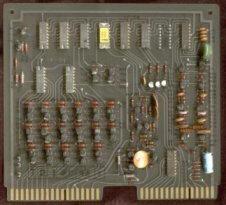
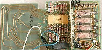
Abstract
This small web page explains the Data Processing System aboard the NASA Space Shuttle (as
of the 1980s,early 1990s) along with unique images taken of my shuttle-flown CPU and IOP
units. |
Birds of a Feather?
How Politics and Culture Affected the Designs of the U.S. Space Shuttle and the Soviet
Buran
by Stephen J. Garber
January 2002
birdsfinalcomplete4.pdf |
Contents- Introduction: The Political and Cultural
Factors Argument; Background on the Two Shuttles; Literature Review
- How Technology and Politics Intertwined: The
U.S. Shuttle's Development; Energiya-Buran Development
- The Impact of Culture: U.S. Technological
Style and the Space Shuttle; Soviet Technological Style and the Energiya-Buran
- Summary and Conclusions
Appendices: - Key U.S. Figures
- Key Soviet Figures
- U.S. Bibliography
- Soviet Bibliography
- Chronology
- Glossary
- Curriculum Vitae
|
Space Shuttle Avionics System
Report No.: NASA-SP-504
January 1, 1989
SP-504 |
Abstract
The Space Shuttle avionics system, which was conceived in the early
1970's and became operational in the 1980's represents a significant
advancement of avionics system technology in the areas of systems and
redundancy management, digital data base technology, flight software, flight
control integration, digital fly-by-wire technology, crew display interface,
and operational concepts. The origins and the evolution of the system are
traced; the requirements, the constraints, and other factors which led to
the final configuration are outlined; and the functional operation of the
system is described. An overall system block diagram is included. |
Manned Spacecraft Automation and Robotics
Jon D. Erickson
Artificial Intelligence and Information Sciences Office
NASA Lyndon B. Johnson Space Center
Houston, TX 77058
Proceedings of the IEEE
Vol. 75, No. 3, March 1987, pp. 417-426
erickson_87 |
Abstract The Space Station holds promise of being a
showcase user and driver of advanced automation and robotics technology. The author
addresses the advances in automation and robotics from the Space Shuttle - with its
high-reliability redundancy management and fault-tolerance design and its remote
manipulator system - to the projected knowledge-based systems for monitoring, control;
fault diagnosis, planning, and scheduling, and the telerobotic systems of the future Space
Station. |